
Modelling for 3D printing
Knowing how 3D modelling works doesn’t automatically mean you are ready to make something printable. Let’s take a look at the limitations and things to keep in mind to correctly translate your digital idea into a real life model of nicely melted plastic filaments.
When facing the task of making a 3D object, there are a few things you should know to avoid ending up with a messy ball of polygons. One thing is modelling to render. This is where you can get away with some confused geometry that will give your architect granny a heart attack. After all, it’s all about the material and the light. Who cares if there are some overlapping parts here and there as long as they aren't visible in your scene, right?
But bringing a 3D figure to the real world is a different ball game. When you’re in the modelling process, you must keep in mind that this will be printed. Remember: 3D printers are very temperamental, to say the least. Even with the most simple of objects, it might decide to mess with your head mid print – wasting hours of your time and metres of filament. So don’t even think about importing messy geometry to the printing software. After all, it won’t go unnoticed by the slicer (you know, that thing that converts polygons to paths for the printer), which will return only a shadow of what was supposed to be a cube.
As mentioned before, my formal training did not include anything about 3D modelling for printing. But the 3D printer I recently built brought a lot of issues on the modelling process to my attention that I didn’t have to worry about before. Remember, what I’m sharing here comes from my personal experience. I might not have all the answers or be always right, but I think this could help you avoid some mistakes I made and save you some time and nerves.
If you are reading this, I’ll assume you are somewhat familiarized with 3D modelling in general. So let’s start with the basic things you should keep in mind and why they are important.
Plan ahead
My boyfriend recently bought a car. He can’t stop talking about it. I, for one, love the fact that he can now drive me to Ikea whenever I need something too big to carry myself. It’s an awesome car, let me tell you that. It’s just not the one I wanted him to buy, but he is happy, so whatever.
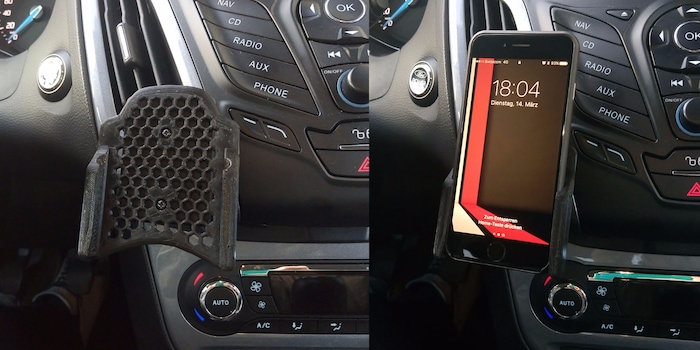
Just like with his commute by train, it didn’t take him long to utter his first complaint. Here’s the thing: After a lot of browsing, he found what was supposed to be the perfect cell phone holder for his car. “Supposed” is the key word here. In reality, he wasn't happy. It was taking up too much space, bringing the phone too close to the wheel and his hand. Luckily, he found a printable solution to replace the piece that was taking up so much space, thanks again to the online community.
You might think this is where it ends, but actually, it’s only the beginning.
The model he found is intended for an iPhone with a thicker case. This minor problem was solved by using two pieces of tape on the sides. But overall, it simply wasn’t aesthetically pleasing, at least not when compared to another piece designed for a OnePlus. My new challenge was to keep the measurements of the iPhone version, while adding the honeycombs of the other model. This wouldl not only save material but also improve the design. But wait, there’s more! I also had to:
- Extend the upper part with a weird curve to hide the base that clips to the car.
- Reduce the space designed for the head of the screws.
- Reduce the space for the cell phone to match the size of my boyfriend’s iPhone including its case.
- Lower the points where the iPhone corners would rest.
- Shorten the lateral arms with a tilted transition from the base.
- Bevel most of the borders.
- Not forget the honeycombs!

In a nutshell: measurements of model one + honeycombs of model two + shape of boyfriend’s draft
First, I tried to reduce the polygons from the iPhone model in a way that allowed me to modify it. It didn’t take long to realize that this was a terrible idea, so I decided to start from scratch.
Keep it simple
When your 3D creation is presented on a screen only, working with as many geometries as you want might make things easier. It can sometimes even save some time when you’re modelling. However, if you want to print the object, a solid single mesh is the way to go.
During my first attempt at modelling this object, I started with a cube. Resizing it, extruding the arms and moving the edges until it was very close to what my boyfriend asked for. This was followed by bevelling the external faces. Then I decided to do a Boolean operation of the rails, holes for the screws and the honeycombs. It was time to bevel the honeycombs. This is when I realized my mistake.

See all the new edges that the Boolean operation created and how the hexagons reacted to the bevel afterwards. Not what I was aiming for
Boolean operations on polygons are awesome! You can join, subtract, keep the intersection or get rid of it with two or more geometries. But that’s the problem; you are working with more than one object and that usually has terrible effects on the final mesh. The results can be visually pleasing, but you’ll notice how some unnecessary polygons or random vertices appear out of the blue. Not only that, but it also takes its toll on the RAM.
Use Boolean operations responsibly.
My whole mesh had so many edges in random places generated by the Boolean subtraction, that the bevelling results were far from ideal.
Time to start again – but properly. This time, instead of a polygonal geometry, I was going to start with a spline. My new process was:
- Draw a path of the outline and honeycombs.
- Combine all the paths and extrude them together.
- Convert the extrusion to polygons.
- Add subdivisions to form the lateral arms that will hold the phone.
- Extrude the outmost faces.
- Bevel the external edges and honeycombs.
- Boolean subtract the rails and the spaces where the screw heads would go.
- Convert objects to a single mesh.
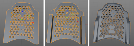
By extruding all the hexagons together with the outline, I avoided creating a crazy amount of polygons on the final mesh
See what I did there? Although I used Booleans this time as well, I did it in a conservative way. In this case, the mesh I got from this operation wasn’t any different from a negative extrusion and bevelling, but it saved me some time. Try to work with as few polygons as possible and if needed, subdivide them right before exporting the file for printing.
It doesn’t hurt to repeat: A solid single mesh is the way to go.
Economy is key
Right from the start, we already considered this factor in the design. By adding the honeycombs, we saved some material while keeping our object solid enough.
In some cases, this solution might be counterproductive. Depending on the printer, such an intricate pattern might take longer to fabricate than a bunch of straight lines. It works in our case because we leave it printing in the morning and it’s done when we are back home. But if you’re not printing at home some places might charge you depending on the time it takes.
You can also avoid wasting filament by designing and placing your project in such a way that the printing software won’t add supports to your object. You can get away with this by modelling objects that aren’t steeper than 45° in relation to the printer bed.
It all comes down to the object, material and printer. You might also want to make it hollow. Just make sure the walls are thick enough. Or just configure the infill in the printer software settings to reduce the amount of filament used for the inner layers of your item. That will also save you some time.
Save as
Not every 3D file will be recognized by the printer software. That’s why I usually export my objects to STL. I like to think it’s like the PDF of the three dimensional world. Of course it also depends on the software, but you can’t go wrong with STL.
Check surface normals
As far as I was concerned, my object was ready to print, but my 3D printer software had news for me. It didn’t look right. What could it be? That’s when I remembered the first – and only – tip I got during my college years related to 3D printing: Check surface normals.
The normal of a surface is an invisible arrow that shows the direction the surface is facing. It might sound obvious to you, but the printer needs to be told which spaces to fill with filament and which to leave alone.
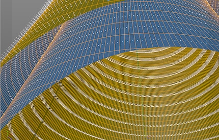
Inside vs outside according to surface normals
Usually you want normals to face outwards, and in most cases they will. Sometimes as a result of all the tinkering, you might inadvertently change that. But fear not, all programmes have a way to solve this. In Cinema 4D it’s called “Align Normals”. In extreme cases, you’d have to “Reverse Normals” too.
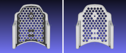
Before and after aligning normals
Object non manifold?
I’ve seen this warning on my printer software so many times without having a clue what it meant. Usually it doesn’t really affect your final product, but better not risk it.
So what is it? In simple words, it’s a type of geometry that’s impossible in the real world. This warning could be triggered by different things:
- Missing faces.
- Loose edges or vertices.
- Inward-facing surfaces.
- Areas too thin to be printed.
All these elements could potentially keep your object from being properly translated by the slicer. The best solution is to avoid them altogether with good modelling habits.
All diese Elemente können verhindern, dass dein Objekt sauber vom Slicer übersetzt wird. Die beste Lösung ist, sie alle von Anfang an zu verhindern, indem man sich gute Modelliergewohnheiten aneignet.
Sometimes, even with the cleanest of models, if it’s quite complex, it’s happened to me that the slicer would erase or misinterpret some elements. For cases like this, there are also some programmes and online services, like Netfabb that could help you clean and fix your STL file.
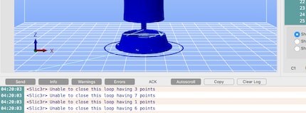
In extreme cases, this is what the slicer will return if you decide to go ahead and try to print a messy geometry
If you don’t really care whether your object is watertight or not and don’t notice any particular anomaly after the slicer has done its job, then proceed at your own risk.
Share it!
Last but not least, share your design with the world. Be part of this revolution and upload your baby!
Who knows, maybe your creation is exactly what someone on the other side of the world was looking for. You could be saving that someone’s girlfriend hours of 3D modelling.
And don’t forget to print and use your new object.
Have fun!
I might be a graphic designer, a Pokémon trainer and tech-savvy but I'm no creative writer. I'm on a non-stop quest against bad design. Since 2014, I call Switzerland my home.
Interesting facts about products, behind-the-scenes looks at manufacturers and deep-dives on interesting people.
Show all


